
If you’re looking to build or tinker with an Odroid N2+ single-board computer, it’s important to have a good understanding of its pinout. A pinout chart is a diagram that shows the layout and functions of the various pins on the board. In this article, we’ll take a closer look at the Odroid N2+ pinout chart and what it can tell you.
The Odroid N2+ is a powerful and versatile single-board computer that’s ideal for a wide range of projects. Whether you’re building a media center, a gaming console, or a smart home hub, the N2+ has the processing power and connectivity options you need. But before you get started, it’s important to understand the pinout chart.
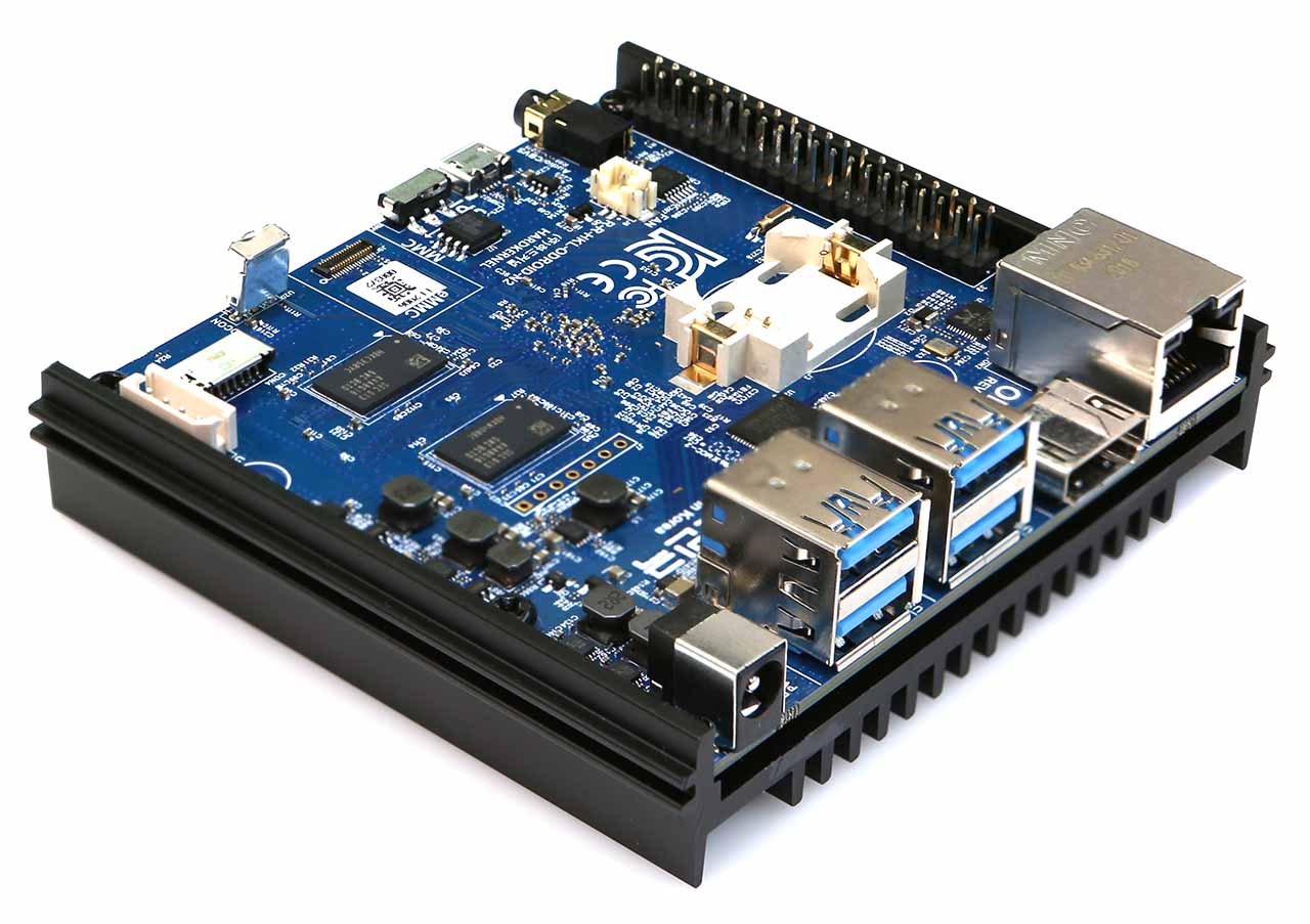
Odroid N2+ Board
At a high level, the Odroid N2+ pinout chart shows the layout and function of the various pins on the board. These pins are used for a variety of purposes, including power, communication, and input/output (I/O) functions. By understanding the pinout chart, you can determine which pins to use for your specific project and how to connect them to other components.
ODROID-N2+ Pinout Chart
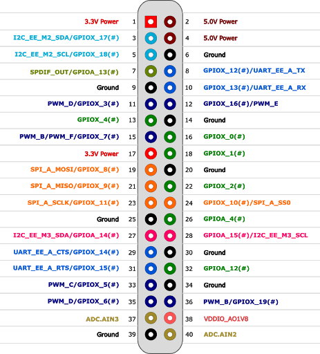
Odroid N2+ Pinout Chart
The Odroid N2+ pinout chart is divided into several sections, each of which shows a different set of pins.
1. Power pins
The power pins on the Odroid N2+ provide the board and any connected components with power. The main power input is a 5.5mm DC jack that accepts a voltage range of 7V to 20V. The 5V and 3.3V output pins provide regulated voltage to external components, and the ground pins provide a common ground for the system.
2. Communication pins
The next section of the pinout chart shows the communication pins. The communication pins on the Odroid N2+ are used for sending and receiving data and for connecting the board to other devices and networks. The UART pins are used for serial communication and can be used to connect the board to devices such as GPS modules and sensors. The SPI pins are used for synchronous serial communication and can be used to connect the board to devices such as displays and flash memory. The I2C pins are used for two-wire serial communication and can be used to connect the board to devices such as accelerometers, temperature sensors, and OLED displays. The Ethernet pins are used for connecting the board to a wired network.
3. Input/Output pins
Finally, the pinout chart shows the I/O pins, which are used for general-purpose input and output functions. The I/O pins on the Odroid N2+ are used for general-purpose input and output functions. The board has a total of 40 GPIO pins that can be used to control external components such as sensors, actuators, and displays. These pins can be configured as inputs or outputs and can be used for a variety of applications, including reading sensor data, controlling motors, and displaying information on a screen. The GPIO pins are divided into four banks of 10 pins each, with each bank having its own set of functions and capabilities.
How to use the pinout chart for your projects
The Odroid N2+ pinout chart is a valuable tool for building and tinkering with the Odroid N2+ single-board computer. With the information provided on the pinout chart, you can connect external components to the board and create custom projects and interfaces that meet your specific needs.
For example, you can use the GPIO pins to control external components such as sensors, actuators, and displays. By connecting sensors to the board, you can read data such as temperature, humidity, and motion, and use this information to control other components or trigger events. By connecting actuators such as motors or lights, you can create interactive projects that respond to input or generate output.
In addition to using the GPIO pins, you can also use the communication pins to connect the Odroid N2+ to other devices and networks. For example, you can use the UART pins to connect the board to a GPS module and read location data, or you can use the I2C pins to connect the board to a temperature sensor and read the ambient temperature. You can also use the Ethernet pins to connect the board to a wired network and access the internet or other networked devices.
Odroid N2+ project ideas
Here are some project ideas that you can build using the pins on the Odroid N2+:
1. Smart Home Controller: You can use the Odroid N2+ to build a smart home controller that can control various devices such as lights, temperature sensors, and smart locks. By using the GPIO pins, you can connect the Odroid N2+ to various sensors and actuators, while using the communication pins to connect the board to the internet and other smart devices. This project can be built using popular home automation platforms like Home Assistant, OpenHAB, or Node-RED.
2. Robot Car: The Odroid N2+ can be used as the brain of a robot car that can be remotely controlled using a smartphone app. By using the GPIO pins to control the motor drivers, and the communication pins to connect the board to the Wi-Fi network, you can build a simple robot car that can be controlled wirelessly. This project can be extended to include sensors such as ultrasonic sensors, light sensors, or cameras for autonomous driving.
3. Weather Station: You can use the Odroid N2+ to build a weather station that can measure various parameters such as temperature, humidity, air pressure, and wind speed. By using the GPIO pins to connect the sensors and actuators, and the communication pins to send data to the internet, you can build a DIY weather station that can provide real-time weather updates.
4. Arcade Machine: The Odroid N2+ can be used to build a retro-style arcade machine that can run various classic games. By using the GPIO pins to connect the buttons and joysticks, and the HDMI port to connect a display, you can build a custom arcade machine that can be used to play various games.
5. Remote Sensing System: The Odroid N2+ can be used to build a remote sensing system that can measure various parameters such as temperature, humidity, and air quality, and transmit the data wirelessly to a remote server. By using the GPIO pins to connect the sensors and the communication pins to send data over Wi-Fi, you can build a DIY remote sensing system that can be used for environmental monitoring or industrial control.
These are just a few project ideas that can be built using the Odroid N2+ pinout chart. By understanding the pinout chart and experimenting with the various pins, you can unlock the full potential of the Odroid N2+ and create innovative and exciting projects.
Conclusion
The Odroid N2+ pinout chart is an essential resource for anyone working with this powerful and versatile single-board computer. By understanding the layout and function of the various pins on the board, you can create custom projects and interfaces that meet your specific needs. Whether you’re a hobbyist, student, or professional, the Odroid N2+ pinout chart is a valuable tool for building and tinkering with this innovative platform.