
The Odroid N2+ is a powerful and versatile single-board computer (SBC) designed by Hardkernel, featuring the Amlogic S922X processor, up to 4GB of RAM, and a plethora of connectivity options. One of the key features of the Odroid N2+ is its support for General Purpose Input/Output (GPIO) and Inter-Integrated Circuit (I2C) communication, which allows users to easily interface with various sensors, actuators, and other electronic components.
Customizing the Odroid N2+ with GPIO and I2C
In this article, we’ll explore how to customize the Odroid N2+ using these interfaces, creating endless possibilities for home automation, robotics, and IoT projects.
Understanding the Odroid N2+ GPIO and I2C Interfaces
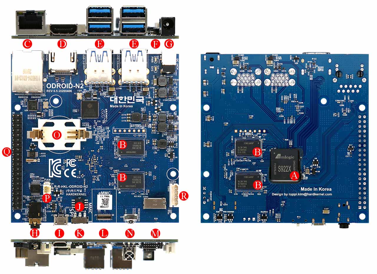
Odroid N2+ Pins and Ports
The Odroid N2+ provides a 40-pin header that exposes a variety of digital and analog interfaces, including GPIO, I2C, SPI, UART, and more. The following sections will provide a brief overview of the GPIO and I2C interfaces:
General Purpose Input/Output (GPIO)
GPIO pins on the Odroid N2+ can be configured as either inputs or outputs, allowing you to control devices like LEDs, buttons, and relays, or read data from sensors, switches, and other peripherals. There are 24 GPIO pins available, providing ample connectivity for most projects. Check our detailed Odroid N2+ Pinout chart article for more information.
Inter-Integrated Circuit (I2C)
I2C is a two-wire, serial communication protocol used to connect low-speed peripherals to a microcontroller or SBC. The Odroid N2+ features two I2C channels, enabling you to connect multiple I2C devices with unique addresses. This is particularly useful for interfacing with sensors, displays, and other components that require simple, reliable communication.
Configuring the Odroid N2+ for GPIO and I2C
Before you can use the GPIO and I2C interfaces on the Odroid N2+, you’ll need to configure the necessary software support. For this tutorial, we’ll assume you’re using the Ubuntu-based Odroid operating system, but the process is similar for other Linux distributions.
Installing the WiringPi Library
WiringPi is a popular library for controlling GPIO on single-board computers. To install WiringPi on your Odroid N2+, open a terminal and enter the following commands:
sudo apt-get update
sudo apt-get install wiringpi
Enabling I2C Support
To enable I2C support on the Odroid N2+, you’ll need to edit the boot configuration file. Open the file by running:
sudo nano /boot/boot.ini
Locate the line starting with “setenv i2c”, and ensure it is not commented out (i.e., no ‘#’ at the beginning of the line). Save and exit the file by pressing ‘Ctrl + X’, followed by ‘Y’, and then ‘Enter’. Reboot your Odroid N2+ for the changes to take effect:
sudo reboot
Using GPIO and I2C with the Odroid N2+
Now that your Odroid N2+ is configured for GPIO and I2C, you can start connecting and controlling various components. In this section, we’ll demonstrate some simple examples to get you started.
Blinking an LED with GPIO
To blink an LED using a GPIO pin, you’ll need an LED, a 220-ohm resistor, and a breadboard. Connect the LED’s anode (longer leg) to a GPIO pin (for example, GPIO 4) through the 220-ohm resistor, and connect the cathode (shorter leg) to a ground pin on the Odroid N2+. Create a new Python script called ‘blink.py’ and enter the following code:
import wiringpi as wp
import time

LED_PIN = 4

wp.wiringPiSetupGpio()
wp.pinMode(LED_PIN, wp.OUTPUT)

while True:
wp.digitalWrite(LED_PIN, wp.HIGH)
time.sleep(1)
wp.digitalWrite(LED_PIN, wp.LOW)
time.sleep(1)
Run the script with the following command:
python3 blink.py
Your LED should now blink once per second. Press ‘Ctrl + C’ to stop the script.
Reading Temperature and Humidity with an I2C Sensor
For this example, you’ll need an I2C temperature and humidity sensor, such as the popular DHT22 or BME280. Connect the sensor to the Odroid N2+ following the manufacturer’s instructions, making sure to connect the SDA and SCL lines to the appropriate I2C pins.
Install the necessary Python library for your sensor, e.g., for the BME280, you can use the ‘bme280’ library:
pip3 install RPi.bme280
Create a new Python script called ‘read_sensor.py’ and enter the following code (adapt the code as necessary for your specific sensor):
import smbus2
import bme280

I2C_PORT = 1
I2C_ADDRESS = 0x76

bus = smbus2.SMBus(I2C_PORT)
calibration_params = bme280.load_calibration_params(bus, I2C_ADDRESS)

def read_sensor():
data = bme280.sample(bus, I2C_ADDRESS, calibration_params)
return data.temperature, data.humidity

while True:
temperature, humidity = read_sensor()
print(f"Temperature: {temperature:.2f} °C, Humidity: {humidity:.2f} %")
time.sleep(5)
Run the script with the following command:
python3 read_sensor.py
The script should output the current temperature and humidity every 5 seconds. Press ‘Ctrl + C’ to stop the script.
Conclusion
In this article, we’ve explored the basics of customizing the Odroid N2+ with GPIO and I2C, enabling you to connect and control various electronic components for your projects. With these fundamental skills, you can now expand your Odroid N2+ applications to include home automation, robotics, and IoT devices. The possibilities are truly endless, limited only by your creativity and ingenuity.