
Do you need to measure voltage, measure frequency, or perform any other time-domain measurements? If so, then an oscilloscope is the perfect measurement tool. Oscilloscopes are used for various activities like measuring voltages across a circuit, analyzing waveforms, etc., mainly because they are fast and accurate. If you don’t have one at home, it can be hard to get one. However, you are lucky you have a Raspberry Pi lying around; you can quickly come up with an oscilloscope.
Build your own Raspberry Pi Oscilloscope
Building a DIY oscilloscope is not as difficult as you may think. Many tutorials on the internet show you how to make one with just a few simple components. Plus, plenty of kits out there will cut down on the headache of buying all the parts separately. This article will give you a step-by-step guide to building an oscilloscope from scratch. Let’s dive in!
Step 1. Setting Up Your Raspberry Pi
Before getting down to the hardware and software requirements/ components we need for this particular project, we need first to set up our Raspberry Pi.
Install an Operating System
Depending on your needs and what you to achieve at the end of the project, there are different Linux-based operating systems that you can install on your Raspberry Pi. We will keep things simple by installing the official Raspberry Pi OS for this post. If you haven’t done that yet, please check out our step-by-step guide, How to install Raspbian on Raspberry Pi.
Setting Up SSH or VNC
Note: This step is meant for users who don’t have a monitor or screen to access their Raspberry Pi. Therefore, if you have one, you can skip this step.
If you don’t have a monitor to access your Raspberry Pi graphical user interface, you can opt for VNC or SSH. Luckily, we already have posts that will give you a step-by-step guide on how to do that. Please check them out below.
Connecting to Wi-Fi & Enabling SSH Without Monitor on Raspberry Pi
How to Set up VNC Server on Raspberry Pi
Step 2. Hardware Requirements
You will need to add some components to your existing kit for the hardware requirements.
- A Raspberry Pi 2 board or later. (We highly recommend using a Raspberry Pi 3 board or later for better performance)
- An 8GB or higher SD card
- An active internet connection. Preferably an Ethernet connection. If you don’t have an ethernet cable and monitor, you can still connect your Pi to Wi-Fi headless. Check out our post – Connecting to Wi-Fi & Enabling SSH Without Monitor on Raspberry Pi.
- Reliable power supply.
- A Light Dependent Resistor (LDR)/ Potentiometer. However, this is an optional requirement meant for testing. For this post, we will use the potentiometer.
- ADS1115 16-Bit ADC. We have discussed more on this component below.
- Breadboard
- Jumper wires
Why the ADS1115 16-Bit ADC
An ADC is a component that converts Analog signals to Digital signals, and the initials are short-term for Analog-to-Digital Converter (ADC). The ADS1115 16-Bit ADC is the best ADC version I have used in my projects. Think of it as an ADC on steroids. It’s versatile and powerful.

ADS1115 16-Bit ADC
If you have previously worked with microcontrollers like ESP 32, ESP 8266, and the Arduino, you know that they come with built-in ADCs. Unfortunately, you have to acquire an external ADC for the Raspberry Pi. Even though you can use any other compatible ADC with your PI, we found the ADS1115 16-Bit ADC a better solution since it’s more powerful and versatile. Additionally, you can find a well-documented guide by Adafruit on using this component.
Step 3. Software Requirements
The software requirements that we will use for this project are mainly Python-based. We will use the matplotlib and drawnow libraries to visualize data and the Adafruit module to communicate with the ADS1115 16-Bit ADC chip.
Step 4. Circuit Design
The ADS1115 ADC has a set of pin specifications, as seen in the image above. For this project, we will use the pins:
- VDD (Positive)
- GND (Ground/ Negative)
- SCL
- SDA
- A0 (We will program the ADC to listen for any incoming signals from this pin)
We will use a Potentiometer with three connections to get the analog input.
- The positive pin
- The negative pin
- The data pin (Used to pass data to the ADC via A0 pin)
So, we aim to rotate the potentiometer in different directions to generate analog signals, which will be passed to the ADS1115 ADC. The ADC will convert these values to digital, and they will be plotted on the Oscilloscope using the matplotlib and drawnow libraries.
The ADS1115 and Raspberry connections that we will use will be as follows:
| ADS1115 | Raspberry Pi |
|---|---|
| VDD | 3.3v |
| GND | GND |
| SDA | SDA |
| SCL | SCL |
To determine the SCL and SDA value on the Raspberry PI, you can use the command below.
gpio readall
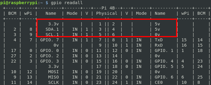
Gpio Readall
From the image above, we can see that;
- 3.3v = First pin
- SDA = Third pin
- SCL = Fifth pin
Tip: You can see the physical pin alignment on the “Physical” column and their specifications on the “Name” columns. For example, Pin 2 and 4 are all 5 volts, and the Grounds pins are labeled with 0 volts in the “Name” column on the right. Additionally, if you encounter the error “Oops – unable to determine board type… model: 17,” don’t panic. Update the gpio version with the command below:
cd /tmp
wget https://project-downloads.drogon.net/wiringpi-latest.deb
sudo dpkg -i wiringpi-latest.deb
We will have positive and negative connections for the potentiometer and the data pin (middle) connected to the A0 pin on the ADS1115 ADC.
Step 5. Enable the 12C Communication Interface
On your Raspberry Pi, execute the command below:
sudo raspi-config
That will open the Raspberry Pi configuration screen. Select the “Interface Options” and hit Enter.
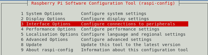
Interface Options
Select the 12C interface and hit enter on the new screen that appears. Next, select the “Enable ” option and hit enter.
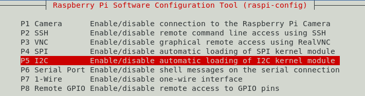
12C Interface
Step 6. Install Dependencies
Before installing the numerous dependencies, update your system with the commands below to ensure running the latest package.
sudo apt update
sudo apt upgrade
Install Adafruit Python Module
When done, execute the command below to install build-essential, git, and several python packages.
sudo apt-get install build-essential python-dev python-smbus git
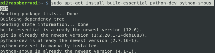
Install Packages
Next, we will install the Adafruit Python using the commands below. Also, ensure you are working on your home directory. You can verify that by executing the command;
cd ~
git clone https://github.com/adafruit/Adafruit_Python_ADS1x15.git
cd Adafruit_Python_ADS1x1z
sudo python3 setup.py install
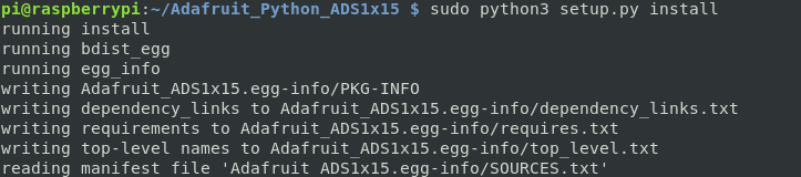
Install Adafruit
Before proceeding further, we need to test whether the ADS1115 ADC can communicate with the Raspberry Pi over the 12C interface. To do that, we will run a simple script that comes with the Adafruit module.
Navigate to the examples directory as shown below and run the script as shown below.
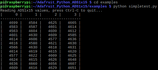
Test 12C
Tip: If you get an error, try running the script with python3 as shown below.
python3 simpletest.py
You can see that the values on column 0 (the A0 pin) are changing with a much higher margin because I am rotating the potentiometer.
Install Matplotlib Python Library
matplotlib is a Python plotting library used for creating static, animated, and interactive visualizations. Execute the command below to install this package on your system.
sudo apt-get install python-matplotlib
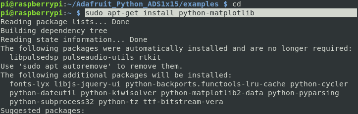
Install Matplotlib
Install Drawnow Python Library
Since the drawnow module isn’t available in the system repository, we will install it with the python-pip module. Execute the commands below.
sudo apt install python3-pip
sudo pip3 install drawnow
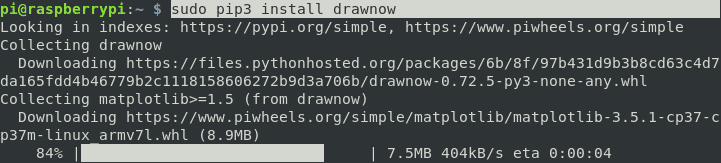
Install Drawnow
Up to this point, we have all the necessary libraries installed to run our Oscilloscope. Now, let’s write the python code. We will call it oscilloscope.py.
#Here, we will import all the necessary modules
import time
import matplotlib.pyplot as plt
from drawnow import *
import Adafruit_ADS1x15
#Here, we will create an ADS1115 ADC (16-bit) instance spcifyiing that
#we are using the ADS1115 ADC
adc = Adafruit_ADS1x15.ADS1115()

GAIN = 1
val = [ ]
cnt = 0
plt.ion()

adc.start_adc(0, gain=GAIN)
print('Reading ADS1x15 channel 0')

#Here, we will define a function to create and set attributes of the graph
def makeFig():
    plt.ylim(-5000,5000)
    plt.title('Osciloscope')
    plt.grid(True)
    plt.ylabel('ADC outputs')
    plt.plot(val, 'ro-', label='Channel 0')
    plt.legend(loc='lower right')
while (True):
    # Here, we read the ADC conversion value
    value = adc.get_last_result()
    print('Channel 0: {0}'.format(value))
    time.sleep(0.5)
    val.append(int(value))
    drawnow(makeFig)
    plt.pause(.000001)
    cnt = cnt+1
    if(cnt>50):
        val.pop(0)
Tip: If you are familiar with Python and the matplotlib library, you can modify the code above to your liking.
Put Everything to Action
Up to this point, we have everything ready. For demonstration, I will connect to my Raspberry Pi via VNC and run the code on Python Idle editor. See the image below.

Oscilloscope
The values are plotted as I rotate the potentiometer. On the left side, you can see the values on channel zero (0), which is the A0 pin on the ADC.
Conclusion
That’s it! We have come to the end of this tutorial. I hope you have the Oscilloscope up and running up to this point. Feel free to share with our readers what other hardware components you included in your project and how you tweaked the code. Do you have any questions regarding this post? Please feel free to leave a comment below.
2 comments
I have tried it, but somehow i have trouble with the i2C-bus. see what happens, when i try to start the example. The same Runtime error happens, when i try to start the copy-pasted code Python routine.
Do you have an idea how to fix this?
pi@raspberrypi:~/Adafruit_Python_ADS1x15/examples $ python3 simpletest.py
Traceback (most recent call last):
File “/home/pi/Adafruit_Python_ADS1x15/examples/simpletest.py”, line 12, in
adc = Adafruit_ADS1x15.ADS1115()
File “/usr/local/lib/python3.9/dist-packages/Adafruit_ADS1x15/ADS1x15.py”, line 319, in __init__
super(ADS1115, self).__init__(*args, **kwargs)
File “/usr/local/lib/python3.9/dist-packages/Adafruit_ADS1x15/ADS1x15.py”, line 82, in __init__
self._device = i2c.get_i2c_device(address, **kwargs)
File “/usr/local/lib/python3.9/dist-packages/Adafruit_GPIO/I2C.py”, line 63, in get_i2c_device
busnum = get_default_bus()
File “/usr/local/lib/python3.9/dist-packages/Adafruit_GPIO/I2C.py”, line 55, in get_default_bus
raise RuntimeError(‘Could not determine default I2C bus for platform.’)
RuntimeError: Could not determine default I2C bus for platform.
I’m getting errors when trying this:
~ $ python oscilloscope.py
RuntimeError: module compiled against API version 0x10 but this version of numpy is 0xd
Traceback (most recent call last):
File “/home/pi/oscilloscope.py”, line 3, in
import matplotlib.pyplot as plt
File “/home/pi/.local/lib/python3.9/site-packages/matplotlib/__init__.py”, line 113, in
from . import _api, _version, cbook, _docstring, rcsetup
File “/home/pi/.local/lib/python3.9/site-packages/matplotlib/rcsetup.py”, line 27, in
from matplotlib.colors import Colormap, is_color_like
File “/home/pi/.local/lib/python3.9/site-packages/matplotlib/colors.py”, line 56, in
from matplotlib import _api, _cm, cbook, scale
File “/home/pi/.local/lib/python3.9/site-packages/matplotlib/scale.py”, line 22, in
from matplotlib.ticker import (
File “/home/pi/.local/lib/python3.9/site-packages/matplotlib/ticker.py”, line 138, in
from matplotlib import transforms as mtransforms
File “/home/pi/.local/lib/python3.9/site-packages/matplotlib/transforms.py”, line 49, in
from matplotlib._path import (
ImportError: numpy.core.multiarray failed to import
Not sure how to fix it.